
I'm not sure why light chaser circuits didn't become a fad in the 70s, which would seem like a natural thing to follow on the heels of the psychedelic era. As far as I know, no electronics kit company offered any such circuit to build until much later. The first I saw the light chaser circuits appear on the consumer market was in the form of Christmas lights in the late 1980s. This was a short-lived fad because the strings didn't last very long. Finally, in the late 1990s, Rainbow Kits offered a circuit that could flash LEDs in the traditional light chaser fashion. Although not too colorful with the red LEDs provided, I built mine using red, yellow, green and blue LEDs.
Another variation of chaser lights are the so-called rope lights. These are light strings contained in a tube, which makes them somewhat easier to handle. For those who don't like the idea of building a kit, these come assembled and ready to go, and cost a bit more. They come in two parts, the light string and the chase controller, each of which cost about $30. You can get them from Gem Sound and American DJ, among other places. Rope lights appear to operate on 120 volts rather than the low voltage of the Rainbow Kits circuit, meaning the two systems are not compatible. Because of their AC voltage requirements, rope lights are much less suitable for battery operation than the Rainbow Kits circuit.
How they work: Light chasers consist of several lighting circuits strung together, usually three or four. Every first light in the string is turned on, then off and the next light is turned on and then off, and so on. Although there are eight lights in the example below, there are only four circuits controlling these lights, which are repeated twice. The two lights that are on at any given time are connected to the same circuit. In the Rainbow Kits light chaser, the four circuits can be repeated up to10 times, giving a string of 40 LEDs.
The circuit that controls the switching is usually a 1 in 10 counter, such as a 4017 IC. Each time this counter is clocked, one of the 10 outputs goes high, hence the name. Since usually only four of the outputs of the counter are needed to control the four lighting circuits, the fifth counter output is usually tied to the reset pin of the chip. When the chip reaches the count of five, it will reset to one. The counter outputs drive transistors, which switches the load. The counter is clocked by an astable multivibrator, such as a 555 timer. There is usually an adjustment to control the speed.
Below is a picture of the Rainbow Kits circuit I built and mounted in a Radio Shack box.
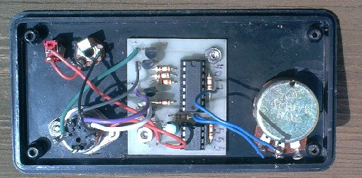
As you can see, the circuit consists of the two ICs, eight resistors, four transistors and one capacitor. I added a pot to control the speed, a power switch, power jack and a 5-pin DIN connector for the light string.
To make the string, I cut apart an old Christmas miniature light string, leaving about 3 inches of wire on each socket. Each LED requires a series resistor depending on the voltage you use and the type of LED. I used 470 ohms for 12 volt operation. The string consists of five wires, a common wire that connects to one end of all the sockets and one wire for each of the four circuits. After rewiring the string, I insulated each connection with clear 1/8 inch heat shrink tubing. See the page on constructing light strings for further details.
The transistors on the circuit board are good for 10 LEDs @ 20 ma each (200 ma), and since there are 4 circuits, it can operate a 40 LED string with 10 LEDs per circuit. That consumes about 140 ma at 12 volts. That makes it practical to operate it on battery power for quite some time, making it ideal for areas without power.
Since it is a low voltage device, the Rainbow Kits light chaser circuit can also be used to trigger strobes
which have a remote input, such as some of the models made by Gem
Sound and
American DJ.
It can chase four strobes, each connected to one of the outputs. I recommend
that you build a basic unit first before you tackle the fancy stuff though.
The Rainbow Kits are cheap enough that you can buy several. I built a basic
unit first, then I decided what additional features I wanted and then built
a more complicated unit. Since the rope light controllers switch line voltage,
they cannot be used to trigger strobes unless the voltage is stepped down to TTL
logic levels, which is what the strobe inputs require. I think it is much saver
to trigger strobes with the Rainbow Kits controller than to try to convert the
output of a rope light controller to safe voltage levels.
Copyright © 2002, Colin Pringle
chr-info.htm